Quick Start Guide
In this Quick Start Guide we'll show how to assemble the Current Sensor - INA2XX (Qwiic) to monitor the power used by a single LED and report the data over I2C using the Qwiic ecosystem. This basic example demonstrates how you would measure current across a DC load connected to the input of the INA2XX. This Quick Start guide assumes users have basic understanding of wiring circuits on a breadboard and working with Arduino development boards. If you're not familiar with these concepts, read on to the full Hookup Guide for more information.
In order to follow along with this guide you'll need a SparkFun Current Sensor - INA2XX (Qwiic) along with the following items:
- RedBoard Plus (or other Arduino-compatible development board)
- Breadboard
- LED
- Resistor (resistor value may change based on your LED)
- Jumper Wires
LED and Qwiic Assembly
Assemble the LED power monitor circuit by following these steps:
- Plug the LED into the breadboard along a single column.
- Connect one side of the resistor to the cathode (-) side of the LED and the other side of the resistor to the breadboard's ground rail.
- Next, take three jumper wires and secure them to the 3-pin screw terminal on the Current Sensor - INA2XX breakout.
- Connect the wires plugged into the IN+ and VBUS terminals to the + rail on the breadboard.
- Connect the wire plugged into the IN- terminal to the same row as the LED's anode (+) pin.
- Connect the RedBoard's 3.3V output to the + rail on the breadboard and one of the RedBoard's ground pins to the "-" rail on the breadboard.
- Plug the Current Sensor breakout into the RedBoard using a Qwiic cable.
- Finally, connect the RedBoard to a computer with a USB-C cable.
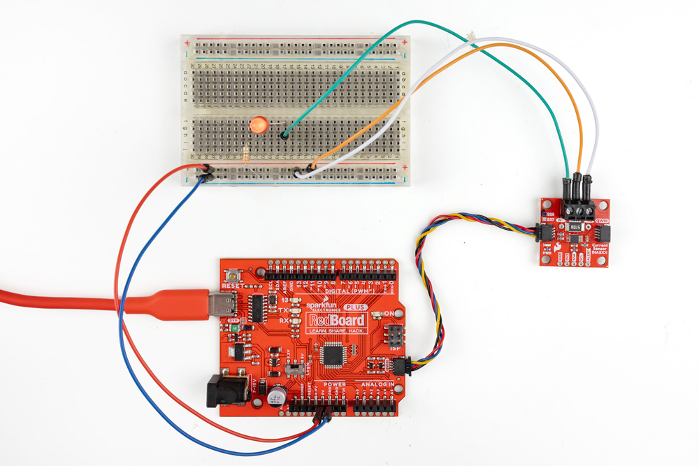
With everything wired up, your circuit should look similar to the photo below:
Arduino Example - Basic Readings
- Open the Arduino IDE.
- Install the SparkFun INA2XX Arduino Library using the Library Manager tool. If you'd prefer to manually install the library, you can download it from the GitHub Repository. This library is built using the SparkFun Toolkit Library so if you do not have that installed already, install it through the Library manager by searching for "SparkFun Toolkit".
- Open Example 01 - Basic Readings from the SparkFun INA2XX library.
- Depending on which version of the current sensor used, comment/uncomment the sensor definition line:
// Uncomment the sensor you're using
SfeINA228ArdI2C myINA;
// SfeINA237ArdI2C myINA;
- Select the Board (SparkFun RedBoard or other board) and Port and click the "Upload" button.
- After the code finishes uploading, open the serial monitor with the baud rate set to 115200.
The code initializes the sensor on the bus and performs an initial calibration for the on-board shunt resistor. After this completes, the code prints out measurements for voltage (V), current (A), power (W) and temperature (°C) every 500ms.